Sign Up

Sign Up to our social questions and Answers Engine to ask questions, answer people's questions, and connect with other people.

Have an account? Sign In
Continue with Facebook
Continue with Google
or use

What is the capital of Egypt? ( Cairo )

Have an account? Sign In Now

Sign In

Login to our social questions & Answers Engine to ask questions answer people's questions & connect with other people.

Sign Up Here
Continue with Facebook
Continue with Google
or use

What is the capital of Egypt? ( Cairo )

Forgot Password?

Don't have account, Sign Up Here

Forgot Password

Volt.Tech

Lost your password? Please enter your email address. You will receive a link and will create a new password via email.

Have an account? Sign In Now

You must login to ask question.

Continue with Facebook
Continue with Google
or use

What is the capital of Egypt? ( Cairo )

Forgot Password?

Need An Account, Sign Up Here

Please briefly explain why you feel this question should be reported.

Please briefly explain why you feel this answer should be reported.

Please briefly explain why you feel this user should be reported.

volt.tech Logo volt.tech Logo
Sign InSign Up

volt.tech

volt.tech Navigation

  • Home
  • About Us
  • Contact Us
Search
Ask A Question

Mobile menu

Close
Ask a Question
  • Tags
  • Category
    • Amplifiers
    • Passives & Protection
    • Clocks & Timing
    • Diodes & Rectifiers
    • FPGAs & PLDs
    • Interface ICs & Transceivers
    • LEDs & Optoelectronics
    • Memories
    • MEMS & Sensors
    • Microcontroller
    • Power Management
    • RF & Microwave
    • Security & Smart Card
    • Motor Drivers
    • Wireless Connectivity
  • Groups
  • Add group
  • Badges
  • Help
  • Home
  • About Us
  • Contact Us
Home/uart

Tag: uart

A UART (Universal Asynchronous Receiver Transmitter) is a piece of logic that sends and receives data on a serial port.

volt.tech Latest Questions

Anonymous
  • 0
Anonymous
Asked: December 30, 2022In: Wireless Connectivity

ESP32-U4WDH and VDD_SDIO power

  • 0

Hi, I got a question that seems not easily answered in the HW documentation. ESP32-U4WDH which has an internal flash, does VDD_SDIO power needs to be connected at all? If so, shall it be connected to 100nF or VCC which is ...Read more

Hi,
I got a question that seems not easily answered in the HW documentation.

ESP32-U4WDH which has an internal flash, does VDD_SDIO power needs to be connected at all?
If so, shall it be connected to 100nF or VCC which is 3v3?

Thanks for your inputs

Read less
espesp32flashU4WDHuartusb
  1. vikas Nagpal
    Added an answer on January 6, 2023 at 9:50 am

    Hello, To run internal flash in ESP32-U4WDH You'd need to connect it to a 100nF capacitor. Thank & Regards

    Hello,

    To run internal flash in ESP32–U4WDH You’d need to connect it to a 100nF capacitor.

    Thank & Regards

    See less
    • 0
    • Share
      Share
      • Share on Facebook
      • Share on Twitter
      • Share on LinkedIn
      • Share on WhatsApp
  • 1 Answer
Answer
harpoon
  • 0
harpoon
Asked: December 26, 2022In: Power Management

ICE3PCS01G Vref(5v) not coming?

  • 0

We have developed 2kW PFC Board with ICE3PCS01G. When I did first power on with 12.15VDC,  Vref not coming from IC. After that I replace the new chip, then it worked fine. But again after changing the nearest components during ...Read more

We have developed 2kW PFC Board with ICE3PCS01G.
When I did first power on with 12.15VDC,  Vref not coming from IC. After that I replace the new chip, then it worked fine. But again after changing the nearest components during troubleshooting, the same problem came (vref gone), But ICOMP=5V is coming. 4 nos of IC got damaged and the same problem coming.

please suggest a solution.

Read less
ICICE3PCS01GuartusbVref
  1. Alex thomas
    Added an answer on December 27, 2022 at 10:05 am

    Thanks for your Question. For the IC, the turn-on voltage is between 11.5~12.9V, turn of is between 10.5~11.9V. So, for 12.15V, if the Vcc is from 12.9V down to it, the IC will run. If VCC is from 10V up to 12.15V, the IC is off and can't work.

    Thanks for your Question.

    For the IC, the turn-on voltage is between 11.5~12.9V, turn of is between 10.5~11.9V.

    So, for 12.15V, if the Vcc is from 12.9V down to it, the IC will run. If VCC is from 10V up to 12.15V, the IC is off and can’t work.

    See less
    • 0
    • Share
      Share
      • Share on Facebook
      • Share on Twitter
      • Share on LinkedIn
      • Share on WhatsApp
  • 1 Answer
Answer
ashishgawade
  • 0
ashishgawade
Asked: December 8, 2022In: Wireless Connectivity

How to use both UART and SPI FLASH boot?

  • 0

Hello, I need to use both UART and SPI interface, FX3’s SPI interface and UART interface are shared, now my SPI is connected to FLASH, I need to power on through SPI FLASH, so I can not use its UART ...Read more

Hello, I need to use both UART and SPI interface, FX3’s SPI interface and UART interface are shared, now my SPI is connected to FLASH, I need to power on through SPI FLASH, so I can not use its UART function, but FX3 has” 16- bit data bus UART SPI I2S” mode. In this mode, UART is mapped to GPIO46-49. Can I use the following settings to enable me to use both UART and SPI FLASH BOOT?

io_cfg.isDQ32Bit = CyFalse;

io_cfg.s0Mode = CY_U3P_SPORT_INACTIVE;
io_cfg.s1Mode = CY_U3P_SPORT_INACTIVE;
io_cfg.useUart = CyTrue;
io_cfg.useI2C = CyFalse;
io_cfg.useI2S = CyFalse;
io_cfg.useSpi = CyTure;
io_cfg.lppMode = CY_U3P_IO_MATRIX_LPP_DEFAULT;
/* No GPIOs are enabled. */
io_cfg.gpioSimpleEn[0] = 0;
io_cfg.gpioSimpleEn[1] = 0x08000000;
io_cfg.gpioComplexEn[0] = 0;
io_cfg.gpioComplexEn[1] = 0;

And, can I still use the virtual COM port function of the UART in this mode?

Read less
bootflashfx3gpio46spiuart
  1. vikas Nagpal
    Added an answer on December 10, 2022 at 10:27 am

    Hi, You can use the" 16- bit Data Bus UART SPI I2S" configuration to use both UART and SPI. Please refer to the available GPIOs for that mode in Table 7 of the FX3 datasheet. As mentioned in the table, you must choose the proper GPIO if you want to use some GPIOs. If you want to use I2S GPIOs you haRead more

    Hi,

    You can use the” 16- bit Data Bus UART SPI I2S” configuration to use both UART and SPI. Please refer to the available GPIOs for that mode in Table 7 of the FX3 datasheet. As mentioned in the table, you must choose the proper GPIO if you want to use some GPIOs. If you want to use I2S GPIOs you have to override using CyU3PDeviceGpioOverride.

    Yes, the virtual COM port will work if you use the below configuration.

    Thanks

    See less
    • 0
    • Share
      Share
      • Share on Facebook
      • Share on Twitter
      • Share on LinkedIn
      • Share on WhatsApp
  • 1 Answer
Answer
Anonymous
  • 0
Anonymous
Asked: November 9, 2022In: Microcontroller

Why USB PCDC Stack Shows an Error?

  • 0

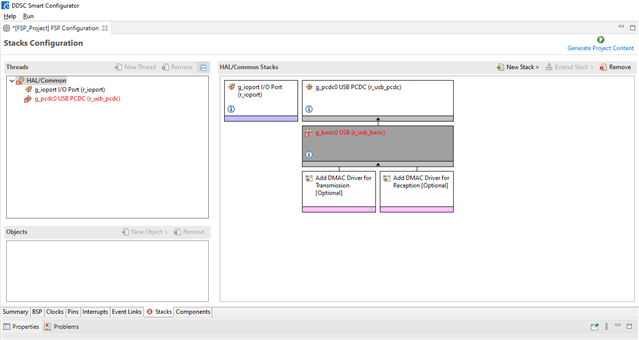
Hello, I am working on the USB. I added the” USB PCDC” stack. But there’s an error” Requires USB clock to be 48 MHz”. How can I fix it?Please see attached screenshot. Thanks.

Hello,
I am working on the USB. I added the” USB PCDC” stack. But there’s an error” Requires USB clock to be 48 MHz”. How can I fix it?

Please see attached screenshot.
Thanks.

Read less
mcupcdcra mcurenesasRenesas Microcontrolleruartusb
  1. nidhi singh
    Added an answer on November 14, 2022 at 10:17 am

    Hello, You need to go to the" Clocks" tab of the FSP configurator and enable the UCLK clock. also, adjust your PLL Mul and UCLK Div to reach the UCLK frequency of 48 MHz. Kind regards,

    Hello,

    You need to go to the” Clocks” tab of the FSP configurator and enable the UCLK clock. also, adjust your PLL Mul and UCLK Div to reach the UCLK frequency of 48 MHz.


    Kind regards,

    See less
    • 0
    • Share
      Share
      • Share on Facebook
      • Share on Twitter
      • Share on LinkedIn
      • Share on WhatsApp
  • 1 Answer
Answer
cleaneatzkitchen
  • 0
cleaneatzkitchen
Asked: November 8, 2022In: Wireless Connectivity

How to use LED Control PWM in low speed mode?

  • 0

Hi! I’m applying the LED Control (LEDC) PWM to control the servo motor, it worked well. And now I need to control further than 8, I’ve checked the ESP32 datasheet, and there have 16 channels can use 8 in High – ...Read more

Hi!

I’m applying the LED Control (LEDC) PWM to control the servo motor, it worked well.
And now I need to control further than 8, I’ve checked the ESP32 datasheet, and there have 16 channels can use 8 in High – speed mode, and 8 in Low – speed mode.
But the ledc library does not support low- speed mode right now, is there any way to use led pwn in low- speed mode?
Like, write the register directly?

thanks!

Read less
datasheetespesp32espressifledledcuart
  1. Alex thomas
    Added an answer on November 11, 2022 at 12:21 pm

    Not sure if the driver does not support all 16 channels. they may just not be supporting the low- speed option of the low- speed channels. But anyway, if you want to poke at the registers yourself, the LED PWM controller is documented in the TRM. Do not forget to actually turn the peripheral on, andRead more

    Not sure if the driver does not support all 16 channels. they may just not be supporting the low- speed option of the low- speed channels. But anyway, if you want to poke at the registers yourself, the LED PWM controller is documented in the TRM. Do not forget to actually turn the peripheral on, and you should get it going enough quickly.


    See less
    • 0
    • Share
      Share
      • Share on Facebook
      • Share on Twitter
      • Share on LinkedIn
      • Share on WhatsApp
  • 1 Answer
Answer
Alex thomas
  • 0
Alex thomas
Asked: November 2, 2022In: Microcontroller

R7FA2L1 UART Recieve Data?

  • 0

Hello, I am experimenting with UART, I’m transferring data every 1 second in my application. When I connect the Rx and Tx pins there’s no trouble.But when I cut the pin attachments. The data I send comes back to me ...Read more

Hello,

I am experimenting with UART, I’m transferring data every 1 second in my application. When I connect the Rx and Tx pins there’s no trouble.
But when I cut the pin attachments. The data I send comes back to me in the form of an interruption. How can I fix this situation? What’s the reason for this situation?

Thanks

Read less
mcumicrocontrollerr7fa2l1ra mcurenesasRenesas Microcontrolleruart
  1. ashishgawade
    Added an answer on November 4, 2022 at 10:29 am

    Hi, Thanks for reaching out to Volt.Tech Engineering Community. The UART- related interrupts can be seen below and call the defined callback function if it's defined. If you do not want a break in you can disable it by configuring SCR( Serial Control Register) properly. Else, you can close UART withRead more

    Hi,

    Thanks for reaching out to Volt.Tech Engineering Community.
    The UART- related interrupts can be seen below and call the defined callback function if it’s defined.

    If you do not want a break in you can disable it by configuring SCR( Serial Control Register) properly. Else, you can close UART withR_SCI_UART_Close() when no physical connection is established between the pins and open it again when there’s a connection.
    Let us know if you solved your issue.

    Regards,

    See less
    • 0
    • Share
      Share
      • Share on Facebook
      • Share on Twitter
      • Share on LinkedIn
      • Share on WhatsApp
  • 1 Answer
Answer
nidhi singh
  • 0
nidhi singh
Asked: September 14, 2022In: Microcontroller

UART WITHOUT INTERRUPT

  • 0

Hello, I’m using RA2L1 and E2 Studio. I want to use UART without interrupt. How can i read and transmit datas?

Hello,

I’m using RA2L1 and E2 Studio. I want to use UART without interrupt. How can i read and transmit datas?

Read less
e2 studiointerruptra2l1renesasuart
  1. ashishgawade
    Added an answer on September 21, 2022 at 10:06 am

    It's possible, but you won't be suitable to use the Read and Write API as handed. You'll have to produce your own which will poll the flags of the SCI SSR( Serial Communications Interface Serial Status Register) You would have to pend on the RDRF for data reception, and TDRE( & potentially TEND)Read more

    It’s possible, but you won’t be suitable to use the Read and Write API as handed. You’ll have to produce your own which will poll the flags of the SCI SSR( Serial Communications Interface Serial Status Register)

    You would have to pend on the RDRF for data reception, and TDRE( & potentially TEND) for data transmission.

    See less
    • 0
    • Share
      Share
      • Share on Facebook
      • Share on Twitter
      • Share on LinkedIn
      • Share on WhatsApp
  • 1 Answer
Answer
techfreak
  • 0
techfreak
Asked: July 30, 2022In: Microcontroller

SCI_UART in Renesas EK-RA4M2

  • 0

Just got the EK-RA4M2. Downloaded example code from here (EK-RA4M2 – Evaluation Kit for RA4M2 MCU Group | Renesas). Connected 1) RXD MISO P410 ——-> TXD Pin of USB-UART 2) TXD MOSI P411 ——-> RXD Pin of USB-UART 3) Common GND as ...Read more

Just got the EK-RA4M2. Downloaded example code from here (EK-RA4M2 – Evaluation Kit for RA4M2 MCU Group | Renesas). Connected

1) RXD MISO P410 ——-> TXD Pin of USB-UART
2) TXD MOSI P411 ——-> RXD Pin of USB-UART
3) Common GND

as readme.txt.

However, there is no serial activity. any suggestions?

Read less
EK-RA4M2renesassciSCI_UARTuart
  1. dev krishnan
    Added an answer on August 1, 2022 at 4:25 pm

    The pins P410, P411 are connected to the SCI0, and pins P601, P602 are connected to the SCI9. Have you changed the channel number in the UART stack like this? Also make sure that the Rx/Tx pins have both CMOS output type:

    The pins P410, P411 are connected to the SCI0, and pins P601, P602 are connected to the SCI9. Have you changed the channel number in the UART stack like this?

    Also make sure that the Rx/Tx pins have both CMOS output type:

    See less
    • 0
    • Share
      Share
      • Share on Facebook
      • Share on Twitter
      • Share on LinkedIn
      • Share on WhatsApp
  • 1 Answer
Answer
techfreak
  • 0
techfreak
Asked: July 29, 2022In: Wireless Connectivity

esp_sleep_enable_uart_wakeup with CONFIG_CONSOLE_UART_CUSTOM configuration

  • 0

I am testing “esp_sleep_enable_uart_wakeup” function. I have connected to UART0 (GPIO3 U0RX, GPIO1 U0TX) an external LTE module and I would like to wake up ESP32 when it is in light sleep but the external module send a particular string on ...Read more

I am testing “esp_sleep_enable_uart_wakeup” function.

I have connected to UART0 (GPIO3 U0RX, GPIO1 U0TX) an external LTE module and I would like to wake up ESP32 when it is in light sleep but the external module send a particular string on the UART0.

I have done a very simple test. It seems to work, but as soon as I change these configuration for CONSOLE debug output from the default to the below ones:

CONFIG_CONSOLE_UART_DEFAULT= CONFIG_CONSOLE_UART_CUSTOM=y CONFIG_CONSOLE_UART_NONE= CONFIG_CONSOLE_UART_CUSTOM_NUM_0= CONFIG_CONSOLE_UART_CUSTOM_NUM_1=y CONFIG_CONSOLE_UART_NUM=1 CONFIG_CONSOLE_UART_TX_GPIO=25 CONFIG_CONSOLE_UART_RX_GPIO=27 CONFIG_CONSOLE_UART_BAUDRATE=115200

It doesn’t work. I would like to use UART1 to send out the debugs because UART0 is occupied to talk with the external module: but the changes in the SDK config (only the one reported above) seems to be the cause of the issue.

How to solve the issue?

Read less
espgpioLTE modulesleep_enableuart
  1. pallavi sharma
    Added an answer on August 1, 2022 at 12:32 pm

    You have to do this PIN_FUNC_SELECT(PERIPHS_IO_MUX_U0RXD_U, FUNC_U0RXD_U0RXD); PIN_FUNC_SELECT(PERIPHS_IO_MUX_U0TXD_U, FUNC_U0TXD_U0TXD);

    You have to do this

    PIN_FUNC_SELECT(PERIPHS_IO_MUX_U0RXD_U, FUNC_U0RXD_U0RXD);
    PIN_FUNC_SELECT(PERIPHS_IO_MUX_U0TXD_U, FUNC_U0TXD_U0TXD);
    See less
    • 0
    • Share
      Share
      • Share on Facebook
      • Share on Twitter
      • Share on LinkedIn
      • Share on WhatsApp
  • 1 Answer
Answer
vikas Nagpal
  • 0
vikas Nagpal
Asked: June 28, 2022In: Microcontroller

Renesas RL78 [R5F102AA] UART Pin configuration

  • 0

I want to configure RX0 and TX0 on pins P16 and P17 for Renesas R5F102AA, is it possible without changing the pin setting on PIOR register?

I want to configure RX0 and TX0 on pins P16 and P17 for Renesas R5F102AA, is it possible without changing the pin setting on PIOR register?

Read less
P16P17PIORrenesasrenesas rl78rl78RL78 [R5F102AA]RX0TX0uartUART Pin
  1. Rutuja
    Added an answer on July 28, 2022 at 3:06 pm

    Do you see the note on page 20 of the Hardware User's Manual? It says clearly that PIOR has to be used to change the function to TxD0/RxD0.

    Do you see the note on page 20 of the Hardware User’s Manual?

    It says clearly that PIOR has to be used to change the function to TxD0/RxD0.

    See less
    • 0
    • Share
      Share
      • Share on Facebook
      • Share on Twitter
      • Share on LinkedIn
      • Share on WhatsApp
  • 2 Answers
Answer
1 2

Sidebar

Ask A Question

Stats

  • Questions 395
  • Answers 381
  • Comments 0
  • Best Answers 9
  • Popular
  • Answers
  • Manoj

    Configuration using .dp vision in Infineon XDPL series IC .

    • 5 Answers
  • Linto

    Renesas RL78/G14 ADC interface code

    • 4 Answers
  • ashishgawade
    ashishgawade added an answer Hello, The USB-serial-JTAG port can usually reset/put the chip into… March 30, 2023 at 11:00 am
  • ashishgawade
    ashishgawade added an answer Hi Nidhi, Thanks for reaching out to Volt.Tech Engineering Community.… March 28, 2023 at 10:13 am
  • ashishgawade
    ashishgawade added an answer Hello@vikas, It's always recommended to use a bleeder of 100 ohms. Vout of the part has an offset… March 24, 2023 at 9:55 am
  • vikas Nagpal
    vikas Nagpal added an answer Hello, The SMPS reduces the power loss when VDD is… March 22, 2023 at 10:30 am
  • nidhi singh
    nidhi singh added an answer Hello Ashish, No, sorry, that kind of setup is physically… March 20, 2023 at 10:45 am

Users

test17802725

test17802725

  • 0 Questions
  • 0 Answers
test45969406

test45969406

  • 0 Questions
  • 0 Answers
RisingLeather

RisingLeather

  • 0 Questions
  • 0 Answers

Explore

  • Tags
  • Category
    • Amplifiers
    • Passives & Protection
    • Clocks & Timing
    • Diodes & Rectifiers
    • FPGAs & PLDs
    • Interface ICs & Transceivers
    • LEDs & Optoelectronics
    • Memories
    • MEMS & Sensors
    • Microcontroller
    • Power Management
    • RF & Microwave
    • Security & Smart Card
    • Motor Drivers
    • Wireless Connectivity
  • Groups
  • Add group
  • Badges
  • Help

Footer

volt.tech

Volt.Tech

Find your spark

About Us

  • About Us
  • Contact Us
  • Groups

Legal Stuff

  • Privacy Policy
  • Faqs

Follow

© 2022 volt.tech. All Rights Reserved
With Love by volt.tech.