Sign Up

Sign Up to our social questions and Answers Engine to ask questions, answer people's questions, and connect with other people.

Have an account? Sign In
Continue with Facebook
Continue with Google
or use

What is the capital of Egypt? ( Cairo )

Have an account? Sign In Now

Sign In

Login to our social questions & Answers Engine to ask questions answer people's questions & connect with other people.

Sign Up Here
Continue with Facebook
Continue with Google
or use

What is the capital of Egypt? ( Cairo )

Forgot Password?

Don't have account, Sign Up Here

Forgot Password

Volt.Tech

Lost your password? Please enter your email address. You will receive a link and will create a new password via email.

Have an account? Sign In Now

You must login to ask question.

Continue with Facebook
Continue with Google
or use

What is the capital of Egypt? ( Cairo )

Forgot Password?

Need An Account, Sign Up Here

Please briefly explain why you feel this question should be reported.

Please briefly explain why you feel this answer should be reported.

Please briefly explain why you feel this user should be reported.

volt.tech Logo volt.tech Logo
Sign InSign Up

volt.tech

volt.tech Navigation

  • Home
  • About Us
  • Contact Us
Search
Ask A Question

Mobile menu

Close
Ask a Question
  • Tags
  • Category
    • Amplifiers
    • Passives & Protection
    • Clocks & Timing
    • Diodes & Rectifiers
    • FPGAs & PLDs
    • Interface ICs & Transceivers
    • LEDs & Optoelectronics
    • Memories
    • MEMS & Sensors
    • Microcontroller
    • Power Management
    • RF & Microwave
    • Security & Smart Card
    • Motor Drivers
    • Wireless Connectivity
  • Groups
  • Add group
  • Badges
  • Help
  • Home
  • About Us
  • Contact Us
Home/spi

Tag: spi

SPI is a low-level 3 or 4 wire serial bus interface with clock (SCLK), data in (MISO) and data out (MOSI). The fourth wire is a Slave Select to uniquely select a device on the bus. This signal is us…

volt.tech Latest Questions

ashishgawade
  • 0
ashishgawade
Asked: December 8, 2022In: Wireless Connectivity

How to use both UART and SPI FLASH boot?

  • 0

Hello, I need to use both UART and SPI interface, FX3’s SPI interface and UART interface are shared, now my SPI is connected to FLASH, I need to power on through SPI FLASH, so I can not use its UART ...Read more

Hello, I need to use both UART and SPI interface, FX3’s SPI interface and UART interface are shared, now my SPI is connected to FLASH, I need to power on through SPI FLASH, so I can not use its UART function, but FX3 has” 16- bit data bus UART SPI I2S” mode. In this mode, UART is mapped to GPIO46-49. Can I use the following settings to enable me to use both UART and SPI FLASH BOOT?

io_cfg.isDQ32Bit = CyFalse;

io_cfg.s0Mode = CY_U3P_SPORT_INACTIVE;
io_cfg.s1Mode = CY_U3P_SPORT_INACTIVE;
io_cfg.useUart = CyTrue;
io_cfg.useI2C = CyFalse;
io_cfg.useI2S = CyFalse;
io_cfg.useSpi = CyTure;
io_cfg.lppMode = CY_U3P_IO_MATRIX_LPP_DEFAULT;
/* No GPIOs are enabled. */
io_cfg.gpioSimpleEn[0] = 0;
io_cfg.gpioSimpleEn[1] = 0x08000000;
io_cfg.gpioComplexEn[0] = 0;
io_cfg.gpioComplexEn[1] = 0;

And, can I still use the virtual COM port function of the UART in this mode?

Read less
bootflashfx3gpio46spiuart
  1. vikas Nagpal
    Added an answer on December 10, 2022 at 10:27 am

    Hi, You can use the" 16- bit Data Bus UART SPI I2S" configuration to use both UART and SPI. Please refer to the available GPIOs for that mode in Table 7 of the FX3 datasheet. As mentioned in the table, you must choose the proper GPIO if you want to use some GPIOs. If you want to use I2S GPIOs you haRead more

    Hi,

    You can use the” 16- bit Data Bus UART SPI I2S” configuration to use both UART and SPI. Please refer to the available GPIOs for that mode in Table 7 of the FX3 datasheet. As mentioned in the table, you must choose the proper GPIO if you want to use some GPIOs. If you want to use I2S GPIOs you have to override using CyU3PDeviceGpioOverride.

    Yes, the virtual COM port will work if you use the below configuration.

    Thanks

    See less
    • 0
    • Share
      Share
      • Share on Facebook
      • Share on Twitter
      • Share on LinkedIn
      • Share on WhatsApp
  • 1 Answer
Answer
nidhi singh
  • 0
nidhi singh
Asked: September 26, 2022In: Microcontroller

RA6T2 Internal Flash?

  • 0
RA6T2 Internal Flash?

Hi, I am curious about what kind of the internal flash of RA6T2 is? Is it NOR flash or NAND flash? According to the program and erase size, it seems to be NOR flash? still, what’s the physical interface of the flash? ...Read more

Hi,

I am curious about what kind of the internal flash of RA6T2 is? Is it NOR flash or NAND flash?
According to the program and erase size, it seems to be NOR flash?

still, what’s the physical interface of the flash? Does it use the SPI or other?
If it was NOR flash.Thanks

Read less
flashinternalnorra6t2renesasRenesas Microcontrollerspi
  1. vikas Nagpal
    Added an answer on October 1, 2022 at 11:23 am

    RA6T2 uses the Renesas proprietary Metal Oxide Nitride Oxide Semiconductor( MONOS) flash technology, it's neither NOR nor NAND. You can search the general web or the Renesas web pages and find information about this. The interface is a direct register grounded via the flash application command interRead more

    RA6T2 uses the Renesas proprietary Metal Oxide Nitride Oxide Semiconductor( MONOS) flash technology, it’s neither NOR nor NAND. You can search the general web or the Renesas web pages and find information about this.

    The interface is a direct register grounded via the flash application command interface( FACI). From the RA6T2 hardware U/ M
    The FCU( flash control unit) controls the programming and erasure of the flash memory. The FACI( flash application command interface) controls the FCU according to the specified FACI commands.

    See less
    • 0
    • Share
      Share
      • Share on Facebook
      • Share on Twitter
      • Share on LinkedIn
      • Share on WhatsApp
  • 1 Answer
Answer
nidhi singh
  • 0
nidhi singh
Asked: September 22, 2022In: Microcontroller

RA4M1, SPI with DMA?

  • 0
RA4M1, SPI with DMA?

Hi, I search for a small example for SPI Master and DMA transfer. So that I can receive e.g. 15 bytes with DMA and get a transfer end to intrude/ message when it’s finished. Thanks in advance!

Hi,

I search for a small example for SPI Master and DMA transfer.
So that I can receive e.g. 15 bytes with DMA and get a transfer end to intrude/ message when it’s finished.

Thanks in advance!

Read less
dmara4m1renesasRenesas Microcontrollerspi
  1. vikas Nagpal
    Added an answer on September 27, 2022 at 11:10 am

    FSP4.0 supports DTC and DMAC transfer interface in the driver Add ther_spi driver to your design Add the DMAC transfer driver to the stack

    FSP4.0 supports DTC and DMAC transfer interface in the driver

    Add ther_spi driver to your design

    Add the DMAC transfer driver to the stack

    See less
    • 0
    • Share
      Share
      • Share on Facebook
      • Share on Twitter
      • Share on LinkedIn
      • Share on WhatsApp
  • 1 Answer
Answer
Techworld
  • 0
Techworld
Asked: August 22, 2022In: Microcontroller

Why RA4W1 – SPI Interbyte Delay

  • 0
Why RA4W1 – SPI Interbyte Delay

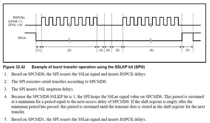
I’m using Renesas FSP to set up the SPI module of an RA4W1 EVK as Master. I’m using burst mode( no negation of the SS between bytes) and there’s an”inter-byte” delay, as shown in figure below( taken from the MCU ...Read more

I’m using Renesas FSP to set up the SPI module of an RA4W1 EVK as Master. I’m using burst mode( no negation of the SS between bytes) and there’s an”inter-byte” delay, as shown in figure below( taken from the MCU datasheet). Is there anyway to get relieve of this delay? I know FSP allows setting the values for timepiece delay, SS negation delay, and coming access delay, but their minimal value is SPI_DELAY_COUNT_1, which results in a delay of 3 CLK cycles between bytes. Some SPI Slaves allow nonstop timepiece with no delay between bytes, which results in advanced outturn.

Thanks for any help you can give!

Read less
delayra4w1spi
  1. Sandeep kumar
    Added an answer on August 22, 2022 at 6:33 pm

    The User's Manual states that you cannot change the SSL negation delay in the SPI module to less than one cycle. However, have you tried utilising the SCI module in SPI Master mode?

    The User’s Manual states that you cannot change the SSL negation delay in the SPI module to less than one cycle.

    However, have you tried utilising the SCI module in SPI Master mode?

    See less
    • 0
    • Share
      Share
      • Share on Facebook
      • Share on Twitter
      • Share on LinkedIn
      • Share on WhatsApp
  • 1 Answer
Answer
vsharma
  • 0
vsharma
Asked: July 30, 2022In: Wireless Connectivity

PSoC interfacing with WiFi module over SPI

  • 0

How to interface a PSoC (e.g. PSoC 63) with a WiFi module (e.g. CY43439)? Is this WiFi-host-driver agnostic to the hardware interface like SPI or SDIO?

How to interface a PSoC (e.g. PSoC 63) with a WiFi module (e.g. CY43439)?

Is this WiFi-host-driver agnostic to the hardware interface like SPI or SDIO?

Read less
psocsdiospiwifi
  1. pallavi sharma
    Added an answer on August 1, 2022 at 2:29 pm

    For the wifi chip that you want to use, driver should have the support or implementation of the interface that you need. For 43439, both the SDIO and SPI interfaces are supported between host and WLAN chip in WHD.

    For the wifi chip that you want to use, driver should have the support or implementation of the interface that you need. For 43439, both the SDIO and SPI interfaces are supported between host and WLAN chip in WHD.

    See less
    • 0
    • Share
      Share
      • Share on Facebook
      • Share on Twitter
      • Share on LinkedIn
      • Share on WhatsApp
  • 1 Answer
Answer
Anonymous
  • 0
Anonymous
Asked: July 28, 2022In: Microcontroller

What is the difference Between SPI inside of SCI and Independent SPI ?

  • 0

 I wanted to clarify the difference between using the SCI module’s SPI pins as opposed to using the SPI pins that aren’t within the SCI module. I was wondering if you could explain why one would choose to use either ...Read more

 I wanted to clarify the difference between using the SCI module’s SPI pins as opposed to using the SPI pins that aren’t within the SCI module. I was wondering if you could explain why one would choose to use either the SPI inside of the SCI module, or use the independent SPI and some design considerations that would be included in making that decision. One more point of confusion for me was why there are pins dedicated to slave selection for SPI communication. To my understanding (which is quite limited), generally with other microcontrollers, you may use a simple GPIO as a slave selection pin, I was wondering if Renesas microcontrollers also had this option or if you have to use the slave selection pins given by the datasheet of the microcontroller.

Read less
gpioscispi
  1. pallavi sharma
    Added an answer on July 29, 2022 at 10:16 am

    The SCI supports a so-called "Simple SPI" mode that has far less capability than the std SPI peripheral.  From the hardware U/M: If your application requirements can be met by the Simple-SPI then it could be used.

    The SCI supports a so-called “Simple SPI” mode that has far less capability than the std SPI peripheral.  From the hardware U/M:

    If your application requirements can be met by the Simple-SPI then it could be used.

    See less
    • 0
    • Share
      Share
      • Share on Facebook
      • Share on Twitter
      • Share on LinkedIn
      • Share on WhatsApp
  • 1 Answer
Answer
vikas Nagpal
  • 0
vikas Nagpal
Asked: July 28, 2022In: Wireless Connectivity

SPI Flash Functions and Unaligned access

  • 0

Question 1: While using the Flash functions in flash_ops.c. It seems that the flash erase functionesp_err_t IRAM_ATTR spi_flash_erase_range(uint32_t start_addr, uint32_t size)is limited to erasing 32768 bytes at a time – is this True?The erase function does not return any ...Read more

Question 1:

While using the Flash functions in flash_ops.c. It seems that the flash erase function

esp_err_t IRAM_ATTR spi_flash_erase_range(uint32_t start_addr, uint32_t size)

is limited to erasing 32768 bytes at a time – is this True?

The erase function does not return any error – however I have a function that I am using to test the SPI flash by writing and reading back data. It only works if I erase smaller chunks at a time.

Question 2:
Do these functions support unaligned access yet?

Read less
flash functionspiunaligned access
  1. pallavi sharma
    Added an answer on July 29, 2022 at 12:18 pm

    The spi_flash_erase_range() function should erase any size, as long as it's offset/size are a multiple of 4096 bytes and the region doesn't overflow the configured flash size. If the erase covers any 32KB aligned blocks, these are erased using the "block erase" function as this is faster than erasinRead more

    The spi_flash_erase_range() function should erase any size, as long as it’s offset/size are a multiple of 4096 bytes and the region doesn’t overflow the configured flash size.

    If the erase covers any 32KB aligned blocks, these are erased using the “block erase” function as this is faster than erasing 8x 4KB sectors individually.

    See less
    • 0
    • Share
      Share
      • Share on Facebook
      • Share on Twitter
      • Share on LinkedIn
      • Share on WhatsApp
  • 1 Answer
Answer
Anonymous
  • 0
Anonymous
Asked: July 25, 2022In: Microcontroller

Differnce between “Simple SPI” and “Standalone SPI”?

  • 0

I have noticed that e2studio uses the term “simple SPI” for the SCI peripherals.  I am setting up a new board where I need two SPI connections for my RA4M3 board.  One to some motor drivers and one to non-QSPI ...Read more

I have noticed that e2studio uses the term “simple SPI” for the SCI peripherals.  I am setting up a new board where I need two SPI connections for my RA4M3 board.  One to some motor drivers and one to non-QSPI external flash.  I will use the one “standalone SPI” that is available, and then one of the SCI peripherals.

Are there any constraints I need to worry about?

Read less
non-Qspi external flashra mcura4m3SCI peripheralsspi
  1. pallavi sharma
    Added an answer on July 29, 2022 at 4:33 pm

    The "simple SPI" mode of the SCI is significantly different than the SPI peripheral. For example the simple-SPI is limited to only 8-databits while the standalone-SPI supports many different bit lengths.  If your needs are met by what the simple-SPI supports there is no reason to avoid to using it.

    The “simple SPI” mode of the SCI is significantly different than the SPI peripheral.

    For example the simple-SPI is limited to only 8-databits while the standalone-SPI supports many different bit lengths.  If your needs are met by what the simple-SPI supports there is no reason to avoid to using it.

    See less
    • 0
    • Share
      Share
      • Share on Facebook
      • Share on Twitter
      • Share on LinkedIn
      • Share on WhatsApp
  • 1 Answer
Answer
Rutuja
  • 0
Rutuja
Asked: July 22, 2022In: Wireless Connectivity

Way to reduce the SPI buffer size.

  • 0

In our project, the parser reads the G-code from the SD card through the SPI interface, using a usual SD.h library. The problem is that regardless of the size of the SD card buffer, the SPI reads 4092 bytes every ...Read more

In our project, the parser reads the G-code from the SD card through the SPI interface, using a usual SD.h library. The problem is that regardless of the size of the SD card buffer, the SPI reads 4092 bytes every time, puts them in the DMA buffer, and reads the next 4092 only when the buffer is free. Because of this, the time for reading g-commands is extremely uneven. Most are read in 20µs, but each 146th is read in over 4500µs. (The average length of g-command is 28 bytes, so 4092/28=146.)
4500µs is approximately equal to the transmission of 4KB at 10MHz. This is a terribly unacceptable time that kills all the advantages of the speed of the microcontroller.

Is there a way to reduce SPI buffer size using arduino IDE? I tried to re-initialize SPI with this construction:

#include “driver/spi_master.h”

#define PIN_NUM_MISO 19

#define PIN_NUM_MOSI 23

#define PIN_NUM_CLK 18 static void spi_init() { spi_bus_config_t buscfg; memset(&buscfg, 0, sizeof(spi_bus_config_t)); buscfg.miso_io_num=PIN_NUM_MISO; buscfg.mosi_io_num=PIN_NUM_MOSI; buscfg.sclk_io_num=PIN_NUM_CLK; buscfg.quadwp_io_num=-1; buscfg.quadhd_io_num=-1; buscfg.max_transfer_sz=64; //default to 4092 if 0 spi_bus_initialize(VSPI_HOST, &buscfg, 1); //DMA channel 1 };

This probably works (message “E (280387) spi: spi_bus_initialize(756): SPI bus already initialized” in console), but in general, the situation does not change. Each 146th g-command is still read in 4500µs. SPI bus is still working through some huge 4KB buffer. And I have totally no idea how to divide it into small chunks of 64-128 bytes.

Read less
dma bufferg-codespi
  1. pallavi sharma
    Added an answer on July 29, 2022 at 5:07 pm

    If you use a RTOS-aware structure (like a ringbuffer, queue, whatever) then you don't need to delay: the push into the buffer will block for you while there's no room available. The amount of elements in a ringbuffer is limited by its size, so you can double, triple, however-many-le buffer the thingRead more

    If you use a RTOS-aware structure (like a ringbuffer, queue, whatever) then you don’t need to delay: the push into the buffer will block for you while there’s no room available. The amount of elements in a ringbuffer is limited by its size, so you can double, triple, however-many-le buffer the things by simply increasing the size of the ringbuffer. Also, perhaps good to mention that by ‘ringbuffer’ I specifically mean the esp-idf ringbuffer construct, as that is RTOS-aware. If you use the bytebuffer mode of that, it would be good.

    See less
    • 0
    • Share
      Share
      • Share on Facebook
      • Share on Twitter
      • Share on LinkedIn
      • Share on WhatsApp
  • 1 Answer
Answer
vsharma
  • 0
vsharma
Asked: July 12, 2022In: Microcontroller

SCI SPI MOSI at 3.7V instead of 3.3V

  • 0

In Renesas RA4M3 with an SCI SPI setup, we have MOSI rising up to 3.7 V instead of 3.3V. After verifying that all input voltage to the processor is 3.3V and testing it with nothing connected to the SCI SPI ...Read more

In Renesas RA4M3 with an SCI SPI setup, we have MOSI rising up to 3.7 V instead of 3.3V. After verifying that all input voltage to the processor is 3.3V and testing it with nothing connected to the SCI SPI as well we could not find reason for MOSI rising up to 3.7V.

Any insight on why this happens?

Read less
mosira4m3renesasscispi
  1. pallavi sharma
    Added an answer on July 13, 2022 at 6:16 pm

    It seems that the motor driver board is sourcing voltage and current into the EVK. 

    It seems that the motor driver board is sourcing voltage and current into the EVK. 

    See less
    • 0
    • Share
      Share
      • Share on Facebook
      • Share on Twitter
      • Share on LinkedIn
      • Share on WhatsApp
  • 1 Answer
Answer
1 2

Sidebar

Ask A Question

Stats

  • Questions 388
  • Answers 374
  • Comments 0
  • Best Answers 8
  • Popular
  • Answers
  • Manoj

    Configuration using .dp vision in Infineon XDPL series IC .

    • 5 Answers
  • Linto

    Renesas RL78/G14 ADC interface code

    • 4 Answers
  • Julian White
    Julian White added an answer Hello, IrDA has hardly been used for a long time,… March 7, 2023 at 10:27 am
  • Julian White
    Julian White added an answer It's not required per se, but it's helpful. The issue… March 4, 2023 at 10:04 am
  • nidhi singh
    nidhi singh added an answer Hi Alex, The exchange mode for MCU boot uses the… March 2, 2023 at 10:37 am
  • Julian White
    Julian White added an answer Hi, Thank you for posting on the Volt.Tech community. Can… February 28, 2023 at 10:04 am
  • nidhi singh
    nidhi singh added an answer Hello, The labeling looks ok F130 = LD2981ABM30TR F133 =… February 23, 2023 at 10:27 am

Users

test27782358

test27782358

  • 0 Questions
  • 0 Answers
test17284313

test17284313

  • 0 Questions
  • 0 Answers
test1856815

test1856815

  • 0 Questions
  • 0 Answers

Explore

  • Tags
  • Category
    • Amplifiers
    • Passives & Protection
    • Clocks & Timing
    • Diodes & Rectifiers
    • FPGAs & PLDs
    • Interface ICs & Transceivers
    • LEDs & Optoelectronics
    • Memories
    • MEMS & Sensors
    • Microcontroller
    • Power Management
    • RF & Microwave
    • Security & Smart Card
    • Motor Drivers
    • Wireless Connectivity
  • Groups
  • Add group
  • Badges
  • Help

Footer

volt.tech

Volt.Tech

Find your spark

About Us

  • About Us
  • Contact Us
  • Groups

Legal Stuff

  • Privacy Policy
  • Faqs

Follow

© 2022 volt.tech. All Rights Reserved
With Love by volt.tech.