Sign Up

Sign Up to our social questions and Answers Engine to ask questions, answer people's questions, and connect with other people.

Have an account? Sign In
Continue with Facebook
Continue with Google
or use

What is the capital of Egypt? ( Cairo )

Have an account? Sign In Now

Sign In

Login to our social questions & Answers Engine to ask questions answer people's questions & connect with other people.

Sign Up Here
Continue with Facebook
Continue with Google
or use

What is the capital of Egypt? ( Cairo )

Forgot Password?

Don't have account, Sign Up Here

Forgot Password

Volt.Tech

Lost your password? Please enter your email address. You will receive a link and will create a new password via email.

Have an account? Sign In Now

You must login to ask question.

Continue with Facebook
Continue with Google
or use

What is the capital of Egypt? ( Cairo )

Forgot Password?

Need An Account, Sign Up Here

Please briefly explain why you feel this question should be reported.

Please briefly explain why you feel this answer should be reported.

Please briefly explain why you feel this user should be reported.

volt.tech Logo volt.tech Logo
Sign InSign Up

volt.tech

volt.tech Navigation

  • Home
  • About Us
  • Contact Us
Search
Ask A Question

Mobile menu

Close
Ask a Question
  • Tags
  • Category
    • Amplifiers
    • Passives & Protection
    • Clocks & Timing
    • Diodes & Rectifiers
    • FPGAs & PLDs
    • Interface ICs & Transceivers
    • LEDs & Optoelectronics
    • Memories
    • MEMS & Sensors
    • Microcontroller
    • Power Management
    • RF & Microwave
    • Security & Smart Card
    • Motor Drivers
    • Wireless Connectivity
  • Groups
  • Add group
  • Badges
  • Help
  • Home
  • About Us
  • Contact Us
Home/module

volt.tech Latest Questions

Alex thomas
  • 0
Alex thomas
Asked: July 12, 2023In: Wireless Connectivity

How to connect AWS IoT Core to EPS Module?

  • 0

Hi, guys. I want your recommendation for AWS IoT Provisioning. I am looking for wifi and ble of EPS Module to connect to AWS IoT Core. I mean this module has wifi and ble. I need it to be ready to use AT Command ...Read more

Hi, guys.

I want your recommendation for AWS IoT Provisioning.

I am looking for wifi and ble of EPS Module to connect to AWS IoT Core.

I mean this module has wifi and ble.

I need it to be ready to use AT Command by the host MCU.

I hope your answer.

Thank You

Read less
awscoreepsesp32iotmcumodule
  1. ashishgawade
    Added an answer on July 13, 2023 at 10:09 am

    Hello, ESP32-S2 module and Nordic nRF52 module are good options for connecting a module with Wi-Fi and BLE capabilities to AWS IoT Core. The AWS IoT Embedded C SDK and AWS IoT Device SDK for Embedded C give easy-to-use APIs for device authentication, shadow management, and MQTT messaging, and you caRead more

    Hello,

    ESP32-S2 module and Nordic nRF52 module are good options for connecting a module with Wi-Fi and BLE capabilities to AWS IoT Core. The AWS IoT Embedded C SDK and AWS IoT Device SDK for Embedded C give easy-to-use APIs for device authentication, shadow management, and MQTT messaging, and you can apply AT commands for communication with a host MCU.

    Thank You

    Ashish

    See less
    • 0
    • Share
      Share
      • Share on Facebook
      • Share on Twitter
      • Share on LinkedIn
      • Share on WhatsApp
  • 1 Answer
Answer
vikas Nagpal
  • 0
vikas Nagpal
Asked: June 13, 2023In: Microcontroller

How to Link node2 and node3 on module CAN1?

  • 0

Hi all, I am testing to configure node 2 and node 3 on module CAN1 to be linked to the inside can bus and out. My final aim is to transfer some data on cun node 1- 2 and receive it on can ...Read more

Hi all,

I am testing to configure node 2 and node 3 on module CAN1 to be linked to the inside can bus and out.

My final aim is to transfer some data on cun node 1- 2 and receive it on can nodes 1- 3 without any processing in the CPU.

no purifier configuration and messages to be transferred, no pack/ unpack function- just as simple as that loop back out.

so I set all needed configurations where I had the node working on normal mode( transfer and receive messages, filter, and messages defined), but also I removed the configurations of the filter and added to the configuration the needed flag

rc = canNodeConfig (& nodeConfig, reeCanNode);// set common configurations

* nodeSfr = IfxCan_getNodePointer (nodeConfig.can,nodeConfig.nodeId); nodeSfr->NPCR.B.LOUT = 1;

for both nodes 1- 2 and 1- 3.

what eventually happens is that I send from an outside source and it looks like the CPU receives (no errors on the bus) but the other bus has errors on it.

how can I be sure that the messages entered into that node? will interrupt for TX/RX receive?
what should I do to test it correctly?
is the setup OK for my purpose? (loop back out)?

Thank You

Read less
can1Infineonmcumicrocontrollermodulenode2node3
  1. Alex thomas
    Added an answer on June 14, 2023 at 10:23 am

    Hello, Connected to the internal CAN bus and loop back the messages received on node 2 to node 3 without any further processing by the CPU. To accomplish this, you can configure both nodes to operate in normal mode and enable loopback mode for node 2 using the LBP bit in the NPCR register. The LBP bRead more

    Hello,

    Connected to the internal CAN bus and loop back the messages received on node 2 to node 3 without any further processing by the CPU.

    To accomplish this, you can configure both nodes to operate in normal mode and enable loopback mode for node 2 using the LBP bit in the NPCR register. The LBP bit sets the loopback mode for the node, allowing it to receive its own transmitted messages.

    Here are the steps you can follow:

    • Configure both nodes to operate in normal mode as you have already done.
    • Enable loopback mode for node 2 by setting the LBP bit in the NPCR register to 1.
    • Transmit a message from an external source to node 2.
    • Verify that node 2 receives the message by checking the RMC and NCR registers.
    • Verify that node 3 receives the same message by checking the RMC and NCR registers.

    You can also use interrupts to receive messages on the nodes. You can enable interrupts for receive and transmit events and write interrupt service routines (ISRs) to handle the events. When a message is received, the corresponding receive interrupt will be triggered, and the data can be read from the received message object.

    Kind Regards,

    Alex Thomas

    See less
    • 0
    • Share
      Share
      • Share on Facebook
      • Share on Twitter
      • Share on LinkedIn
      • Share on WhatsApp
  • 1 Answer
Answer
Alex thomas
  • -1
Alex thomas
Asked: April 20, 2023In: Wireless Connectivity

How to Use 5V VIN pin in ESP32 LoRa SX1276 Microcontroller?

  • -1

Hey, I am creating a smash barrier controller with ESP32 SX1276 LoRa microcontroller, and I require a 5V external power force, but I can not find anywhere which pin of 5V is the VIN one, I do not want to ...Read more

Hey, I am creating a smash barrier controller with ESP32 SX1276 LoRa microcontroller, and I require a 5V external power force, but I can not find anywhere which pin of 5V is the VIN one, I do not want to ruin my module, so does anyone know this particular module and which of the 5V pins is the VIN one? I have uploaded the board setup for reference purposes. If you want any extra information please let me know.

Thank You

Alex Thomas

Read less
esp32espressifloramicrocontrollermodulepinsx1276vin
  1. nidhi singh
    Added an answer on April 21, 2023 at 10:04 am
    This answer was edited.

    Hello, They are likely both connected to the Vin signal; check with a multimeter if there is continuance between the two pins if you want to make sure. Thank You Nidhi Singh

    Hello,

    They are likely both connected to the Vin signal; check with a multimeter if there is continuance between the two pins if you want to make sure.

    Thank You

    Nidhi Singh

    See less
    • 0
    • Share
      Share
      • Share on Facebook
      • Share on Twitter
      • Share on LinkedIn
      • Share on WhatsApp
  • 1 Answer
Answer
Alex thomas
  • 0
Alex thomas
Asked: December 10, 2022In: Wireless Connectivity

How to Power ESP32 Devkitc v4 Module from Regulated 5v?

  • 0

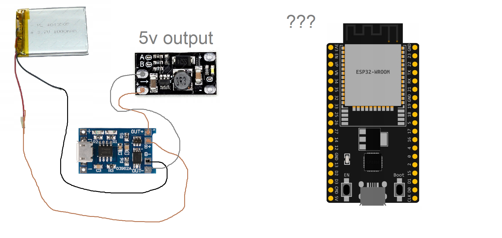
Hello, I’ve lipo battery connected to tp4056 (with protection), and it’s connected to a 5v output boost module. How can I connect it to the board? And also can I have a USB connection to the board without burning the ...Read more

Hello, I’ve lipo battery connected to tp4056 (with protection), and it’s connected to a 5v output boost module. How can I connect it to the board? And also can I have a USB connection to the board without burning the module?

Read less
devkitcesp32lipomoduletp4056usb
  1. nidhi singh
    Added an answer on December 14, 2022 at 10:17 am

    Hii, From boost converter (u really do not need it but anyway.) to ESP32- wroom 5v pin (from photo bottom left pin) and from charge- to GND (ANY OF THEM). Can connect a USB to the ESP32 WROOM directly (with this connection in place, no need to disconnect) and flash any firmware you want, also disconRead more

    Hii, From boost converter (u really do not need it but anyway.) to ESP32- wroom 5v pin (from photo bottom left pin) and from charge- to GND (ANY OF THEM).

    Can connect a USB to the ESP32 WROOM directly (with this connection in place, no need to disconnect) and flash any firmware you want, also disconnect the USB, and if the battery is full and it’ll work.
    Can also connect a USB to the TP4056 for charging WHILE it feeds the ESP32.

    You really do not need the Boost since the TP4056 will output3.7 v and you have a 1000mah (milli amps hour) battery which will allow the ESP32 to work for a good while (depending on what u are doing etc) before recharging. In this configuration just connect the OUT to3.3 v (top left) and OUT- to any GND pin.
    But u will need a USB connection to load any firmware and later disconnect it and let the battery feed the ESP32.

    Enjoy.

    See less
    • 0
    • Share
      Share
      • Share on Facebook
      • Share on Twitter
      • Share on LinkedIn
      • Share on WhatsApp
  • 1 Answer
Answer
vikas Nagpal
  • 0
vikas Nagpal
Asked: October 26, 2022In: Wireless Connectivity

ESP32-C3-MINI-1-H4 RTC External Power and Chip Enable?

  • 0

Hello, I notice the supply for the RTC is also connected to the general 3V3 supply on the schematic for the ESP32- C3-MINI-1-H4 module. If I supply3.3 V power to the ESP32- C3-MINI-1-H4 but have the enable line low, so chip ...Read more

Hello, I notice the supply for the RTC is also connected to the general 3V3 supply on the schematic for the ESP32- C3-MINI-1-H4 module.

If I supply3.3 V power to the ESP32- C3-MINI-1-H4 but have the enable line low, so chip impaired, will the RTC keep on running if it has been set before?

Or for the RTC to remain running but the chip powered down will I need to produce my own layout to break out the RTC 3V3 pin and thus I won’t be suitable to use the ESP32- C3-MINI-1-H4 module?

Thanks

Read less
chipesp32esp32c3mini1externalpowermodulertc
  1. ashishgawade
    Added an answer on October 28, 2022 at 9:46 am

    Neither. The ESP32-C3 needs to have all 3.3 V power pins powered at the same time, it's not possible to power the RTC domain independently. Disabling the chip using EN will shut down the wholeness of the chip, including the RTC. To make use of the RTC in low-power mode, you need to use software to pRead more

    Neither. The ESP32-C3 needs to have all 3.3 V power pins powered at the same time, it’s not possible to power the RTC domain independently. Disabling the chip using EN will shut down the wholeness of the chip, including the RTC. To make use of the RTC in low-power mode, you need to use software to put the chip into a deep sleep.

    See less
    • 0
    • Share
      Share
      • Share on Facebook
      • Share on Twitter
      • Share on LinkedIn
      • Share on WhatsApp
  • 1 Answer
Answer
vikas Nagpal
  • 0
vikas Nagpal
Asked: September 13, 2022In: Wireless Connectivity

Connecting ESP32 Cam to a Multimeter?

  • 0

I would like to know if it was possible ever to keep connected the micro usb of the esp32- cam- mb to load the module and in the meantime check the consumption( Ampere) from a multimeter. I tried to connect the multimeter in any way but failed Thanks

I would like to know if it was possible ever to keep connected the micro usb of the esp32- cam- mb to load the module and in the meantime check the consumption( Ampere) from a multimeter.

I tried to connect the multimeter in any way but failed
Thanks

Read less
esp32esp32-cam-mbmodulemultimeter
  1. ashishgawade
    Added an answer on September 20, 2022 at 5:03 pm

    Sure. Take a USB lead, cut off the external isolation, find the red wire, cut it in two, and connect the multimeter in between. Make sure the internal resistance/ burden voltage of your multimeter isn't too high if the voltage drop of the multimeter is too high, your ESP32 may brown out. ( You can tRead more

    Sure. Take a USB lead, cut off the external isolation, find the red wire, cut it in two, and connect the multimeter in between. Make sure the internal resistance/ burden voltage of your multimeter isn’t too high if the voltage drop of the multimeter is too high, your ESP32 may brown out. ( You can try switching to the 10A range when you suppose that happens.)

    See less
    • 0
    • Share
      Share
      • Share on Facebook
      • Share on Twitter
      • Share on LinkedIn
      • Share on WhatsApp
  • 1 Answer
Answer
vsharma
  • 1
vsharma
Asked: August 22, 2022In: Wireless Connectivity

How SPI DMA in ESP32-S2-WROOM

  • 1

How we’re implemented SPI poling in ESP32- S2- WROOM module. But now I need to apply SPI DMA for Transmit and admit. is ESP32- S2- WROOM module supports SPI DMA? actually we searched in github, I find SPI DMA stack ...Read more

How we’re implemented SPI poling in ESP32- S2- WROOM module. But now I need to apply SPI DMA for Transmit and admit.
is ESP32- S2- WROOM module supports SPI DMA?
actually we searched in github, I find SPI DMA stack but in that no DMA related functions.

Read less
dmaesp32moduletransmit
  1. Techworld
    Added an answer on August 24, 2022 at 9:39 am

    Given that you're using the ESP-IDF SPI driver and assign a DMA channel to the host driver when initializing it, you're already using DMA. The driver will use DMA for data transfers automatically.

    Given that you’re using the ESP-IDF SPI driver and assign a DMA channel to the host driver when initializing it, you’re already using DMA. The driver will use DMA for data transfers automatically.
    See less
    • 0
    • Share
      Share
      • Share on Facebook
      • Share on Twitter
      • Share on LinkedIn
      • Share on WhatsApp
  • 1 Answer
Answer
Anonymous
  • 0
Anonymous
Asked: May 27, 2022In: Wireless Connectivity

LoRa module communication failure issue

  • 0

When two LoRa modules cannot communicate with each other, what are the steps for failure detection?

When two LoRa modules cannot communicate with each other, what are the steps for failure detection?

Read less
communicationconnectivity issueloramodulerenesas
  1. nakhtar
    Added an answer on May 27, 2022 at 5:59 pm

    Hi, First check whether the SPI communication is successful, the successful sign is that the version value of the read chip is 0x12, the DIO0 pin is responsible for notifying the MCU that the reception is completed and check whether the DIO0 pin configuration is normal. The configuration parametersRead more

    Hi,

    First check whether the SPI communication is successful, the successful sign is that the version value of the read chip is 0x12, the DIO0 pin is responsible for notifying the MCU that the reception is completed and check whether the DIO0 pin configuration is normal. The configuration parameters of LoRa should be consistent, including frequency, spreading factor, bandwidth, coding rate, preamble length, frequency hopping enable, syncword, and low-rate optimization; if one of the above parameters is different, communication cannot be performed.

    See less
    • 0
    • Share
      Share
      • Share on Facebook
      • Share on Twitter
      • Share on LinkedIn
      • Share on WhatsApp
  • 1 Answer
Answer

Sidebar

Ask A Question

Stats

  • Questions 450
  • Answers 435
  • Comments 0
  • Best Answers 9
  • Popular
  • Answers
  • Manoj

    Configuration using .dp vision in Infineon XDPL series IC .

    • 5 Answers
  • Linto

    Renesas RL78/G14 ADC interface code

    • 4 Answers
  • Alex thomas
    Alex thomas added an answer Hello, Right, existing LED drivers all have PWM engines. It… September 19, 2023 at 11:10 am
  • Julian White
    Julian White added an answer Hello, You should set handshake after setting property RtsEnable =… September 14, 2023 at 10:59 am
  • Julian White
    Julian White added an answer Hello @Vikas, Thanks for posting your question online. Yes, one… September 12, 2023 at 10:33 am
  • Alex thomas
    Alex thomas added an answer Hi @sachinsharma, XDPL8221 has a PWM dimming interface which is… September 4, 2023 at 11:01 am
  • ashishgawade
    ashishgawade added an answer Hello I assume that you're using our STEVAL_ISC005V1 board and… August 29, 2023 at 10:32 am

Users

test26249294

test26249294

  • 0 Questions
  • 0 Answers
test31128432

test31128432

  • 0 Questions
  • 0 Answers
test9280286

test9280286

  • 0 Questions
  • 0 Answers

Explore

  • Tags
  • Category
    • Amplifiers
    • Passives & Protection
    • Clocks & Timing
    • Diodes & Rectifiers
    • FPGAs & PLDs
    • Interface ICs & Transceivers
    • LEDs & Optoelectronics
    • Memories
    • MEMS & Sensors
    • Microcontroller
    • Power Management
    • RF & Microwave
    • Security & Smart Card
    • Motor Drivers
    • Wireless Connectivity
  • Groups
  • Add group
  • Badges
  • Help

Footer

volt.tech

Volt.Tech

Find your spark

About Us

  • About Us
  • Contact Us
  • Groups

Legal Stuff

  • Privacy Policy
  • Faqs

Follow

© 2022 volt.tech. All Rights Reserved
With Love by volt.tech.