Please share the information about IOT tool kit.
Please share the information about IOT tool kit.
Read lessSign Up to our social questions and Answers Engine to ask questions, answer people's questions, and connect with other people.
Login to our social questions & Answers Engine to ask questions answer people's questions & connect with other people.
Volt.Tech
Lost your password? Please enter your email address. You will receive a link and will create a new password via email.
Please briefly explain why you feel this question should be reported.
Please briefly explain why you feel this answer should be reported.
Please briefly explain why you feel this user should be reported.
Please share the information about IOT tool kit.
Please share the information about IOT tool kit.
Read lessHello,I’m looking for SPI demo code for TLE6208- 6G.Please share demo code to check the functionality of drivers.Also, How i can produce non-overlap dead time for switching? is it formerly charged in IC or do i need to do some ...Read more
Hello,
I’m looking for SPI demo code for TLE6208- 6G.
Please share demo code to check the functionality of drivers.
Also, How i can produce non-overlap dead time for switching? is it formerly charged in IC or do i need to do some revision in Firmware code?
Thanks,
Cocobella
Read lessHi Cocobella, Generally, dead time is set by the MCU instead of by the driver. The dead time depends on the generated PWM by the MCU. The exacted dead time (t_DHL/t_DLH) in the driver is mostly for defense. So, you may have to make changes in the MCU for expected dead time. Thanks & Regards, JulRead more
Hi Cocobella,
Generally, dead time is set by the MCU instead of by the driver.
The dead time depends on the generated PWM by the MCU. The exacted dead time (t_DHL/t_DLH) in the driver is mostly for defense. So, you may have to make changes in the MCU for expected dead time.
Thanks & Regards,
Julian
Hello Volt Tech,I need to know the difference between IIS3DWB and ISM330DLC.Why we’re calling IIS3DWB as vibration detector while ISM330DLC has accelerometer inside with the same specifications as in IIS3DWB?Which is better in covering the vibration in motors?Thanks
Hello Volt Tech,
I need to know the difference between IIS3DWB and ISM330DLC.
Why we’re calling IIS3DWB as vibration detector while ISM330DLC has accelerometer inside with the same specifications as in IIS3DWB?
Which is better in covering the vibration in motors?
Thanks
Read lessHi @Asher Alvis, Supposing a vibration of the same magnitude order of RPMs of the rotating motor, IIS3DWB is the only device suitable to detect 10kHz vibration, since its ODR is 26.6 kHz and the maximum detectable frequency is ODR/2. Regards Ashish
Hi Asher Alvis Alvis,
Supposing a vibration of the same magnitude order of RPMs of the rotating motor, IIS3DWB is the only device suitable to detect 10kHz vibration, since its ODR is 26.6 kHz and the maximum detectable frequency is ODR/2.
Regards
Ashish
Hello Volt Tech Team, Hope you’re doing well and everything is going well from your end. We’ve one doubt regarding 32 KHz XTAL which is being applied to multiple ESP32-based designs and we’ve also used from reference design in our product. But I ...Read more
Hello Volt Tech Team,
Hope you’re doing well and everything is going well from your end.
We’ve one doubt regarding 32 KHz XTAL which is being applied to multiple ESP32-based designs and we’ve also used from reference design in our product.
But I would like to see what will be if we take off that XTAL like will it create any issue with any hardware or software working functionality if we remove it? I believe it’s mostly applied to RTC Sleep and Wakeup Mechanism.
So, would you please check and confirm from your end regarding real usage with dependencies if any for that XTAL?
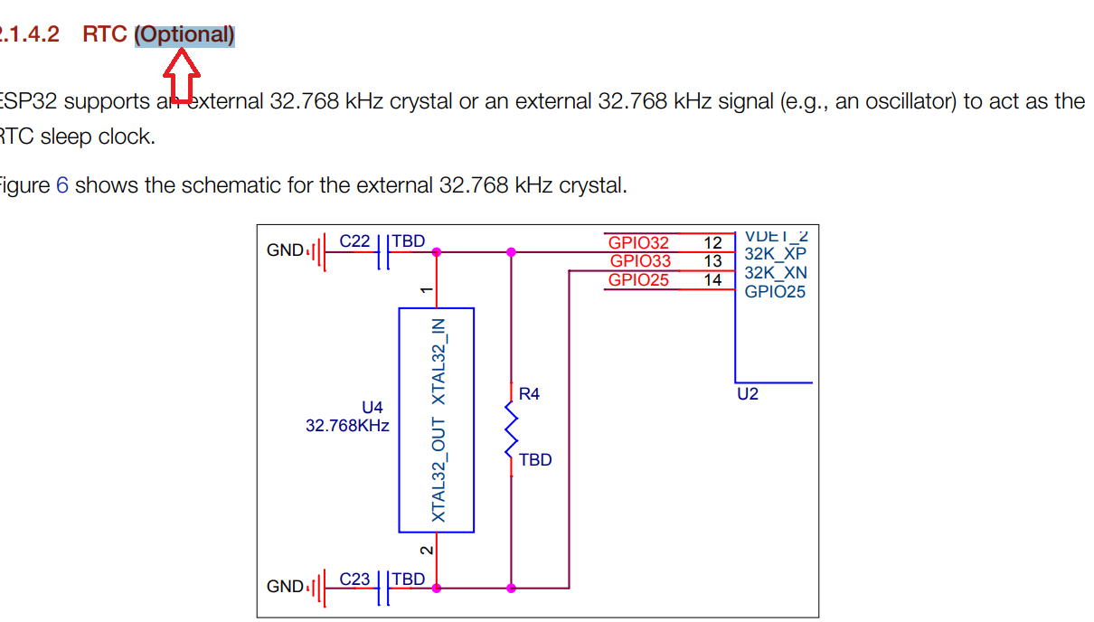
Regards,
Sachin
Read lessHello, It's required if you want stable (<5% drift) timekeeping in sleep modes where the 40 MHz crystal is switched off i.e. deep sleep, or if you want BT modem sleep. Thank You Julian White
Hello,
It’s required if you want stable (<5% drift) timekeeping in sleep modes where the 40 MHz crystal is switched off i.e. deep sleep, or if you want BT modem sleep.
Thank You
Julian White
See lessHi, Community,I understand that KitProg3 or after tools (e.g. MiniProg4) are needed to debug systems created with the Modus tool box. However, I would want to use KitProg2 (e.g. MiniProg3) to load Program Flash. For the programming tool, I consider ...Read more
Hi, Community,
I understand that KitProg3 or after tools (e.g. MiniProg4) are needed to debug systems created with the Modus tool box. However, I would want to use KitProg2 (e.g. MiniProg3) to load Program Flash. For the programming tool, I consider applying Modus tool box programmer or PSoC programmer. I would want to load Flash on a PSoC4100S Maximum device.
Best Regards,
Robert Gandell
Hi, As you understand, PSoC4100S MAX simply supports ModusToolbox. Therefore, the PSoC Creator and PSoC programmer shouldn't be suitable to recognize PSoC4100S MAX devices. Generated by ModusToolbox are simply compatible with ModusToolbox programmer (older name Cypress programmer) and can not be wriRead more
Hi,
As you understand, PSoC4100S MAX simply supports ModusToolbox.
Therefore, the PSoC Creator and PSoC programmer shouldn’t be suitable to recognize PSoC4100S MAX devices.
Generated by ModusToolbox are simply compatible with ModusToolbox programmer (older name Cypress programmer) and can not be written applying PSoC Programmer.
And KitProg2 (or MiniProg3) isn’t compatible with ModusToolbox programmer. From the above, PSoC4S MAX only supports ModusToolbox programmer and KitProg3 (or MiniProg4).
I tried the following using CY8CKIT-145, which is compatible with both ModusToolbox and PSoC Creator.
1. Create a project with CY8CKIT-145 BSP with ModusToolbox.
2. Program after building and check operation (KitProg3 firmware version2.5.1383)
3. KitProg firmware update from PSoC Programmer (KitProg3 firmware version2.1.878)
4. Program after setting the HEX file generated by ModusToolbox in PSoC Programmer.
5. It can not be read rightly because the file types are different as shown below.

Since the HEX file types are different between ModusToolbox and PSoC Creator, you can see that HEX files generated by ModusToolbox aren’t compatible with PSoC Programmer.
Thanks & Regards,
Hello,I would like to apply Renesas Motor Workbench but I do not understand all the parameters that can be manipulated.I apply the program RA6T2_MCILV1_SPM_LESS_120_E2S_V110 and then’s the list of parameters:Does anyone experience ...Read more
Hello,
I would like to apply Renesas Motor Workbench but I do not understand all the parameters that can be manipulated.
I apply the program RA6T2_MCILV1_SPM_LESS_120_E2S_V110 and then’s the list of parameters:
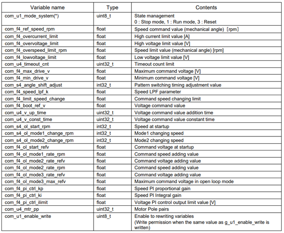
Does anyone experience where to discover clarification on this subject?
Thank you in advance.
Best Regards,
Nathan
Read lessHello Nathan, These parameters are internal variables of the vector control c design. Let us explain some of them ref_speed_rpm: it's the quickness that an external user sets via a potentiometer.over the current limit: the max current value, over this value you have the faulty condition of the motorRead more
Hello Nathan,
These parameters are internal variables of the vector control c design.
Let us explain some of them
ref_speed_rpm: it's the quickness that an external user sets via a potentiometer.
over the current limit: the max current value, over this value you have the faulty condition of the motor
overvoltage_limit: maximum dc voltage, over this value you have over voltage at dc link of your topology
overspeed_limit_rpm: is the maximum speed that your motor has designed
lowvoltage_limit: the minimal voltage that requires the inverter to drive your motor
 limit_speed_change: the maximum acceptable change of the motor speed that the user can give
However, please feel free to ask, If you can not understand any specific system parameter.
Best Regards,
Vikas Nagpal
Hello,Why there is no 480…..500 MHz variants of H5, like in the H7 range?Thank You
Hello,
Why there is no 480…..500 MHz variants of H5, like in the H7 range?
Thank You
Hello, STM32H7 can apply code from RAM too. Some version figures are in the data sheets to compare. STM32H750, 480 MHz 1027 DMIPS,2.14 DMIPS/ MHz( Dhrystone2.1) ADC up to3.6 MSPS STM32H503, 250 MHz 375 DMIPS (Dhrystone2.1) 1.5 DMIPS/ MHz (Drystone2.1) 1023 CoreMark (4.092 CoreMark/ MHz) ADC up to 2Read more
Hello,
STM32H7 can apply code from RAM too.
Some version figures are in the data sheets to compare.
STM32H750, 480 MHz 1027 DMIPS,2.14 DMIPS/ MHz( Dhrystone2.1)
ADC up to3.6 MSPS
STM32H503, 250 MHz 375 DMIPS (Dhrystone2.1) 1.5 DMIPS/ MHz (Drystone2.1)
1023 CoreMark (4.092 CoreMark/ MHz)
ADC up to 2.5 MSPS
So. the CM33 core doesn’t automatically supply more bang for MHz.
Thank You
Hello,Let’s say I want to design an ESP32-S3 board with 8 MB of flash and 8 MB of PSRAM. I see that there are a many possible ways I could do this I could use an ESP32- S3FN8 with 8 ...Read more
Hello,
Let’s say I want to design an ESP32-S3 board with 8 MB of flash and 8 MB of PSRAM. I see that there are a many possible ways I could do this I could use an ESP32- S3FN8 with 8 MB of in-package flash and add an external 8 MB PSRAM chip, or I could apply an ESP32- S3R8 (V) with 8 MB of in-package PSRAM and add an external 8 MB flash chip. What are the relative advantages and downsides of doing it each way, if any?
It looks like I could even apply the base ESP32-S3 (with no built-in flash or PSRAM) and add both an 8 MB flash chip and an 8 MB PSRAM chip. Is there any reason I’d need to do it that way?
Thanks & Regards
Read lessHello, There is not much then, anyway, it is good. There are many effects to watch out for that I can come up with You may need to apply octal flash or PSRAM. Those tend to have a more complicated package (BGA), so you may need to have that on-package in the ESP32S3 to save you the hassle. Board spaRead more
Hello,
There is not much then, anyway, it is good. There are many effects to watch out for that I can come up with
Thank You
Alex
Hello everyone,I make a new RA2E2 hardware board. But it can’t start up flash programmer connect fail with SCI, and SWD connect fail too.I check some pinsVCC3.3 VVCL1.5 VP201/ MD can switch 0V or 3.3 V with key.RES can switch ...Read more
Hello everyone,
I make a new RA2E2 hardware board. But it can’t start up flash programmer connect fail with SCI, and SWD connect fail too.
I check some pins
VCC3.3 V
VCL1.5 V
P201/ MD can switch 0V or 3.3 V with key.
RES can switch 0 V or3.3 V with key.
timing is right when PC send data to RA2E2 board.
But RA2E2 have no any response.
Are there any other debug way for RA2E2? or any user guide doc for this issue?
Thanks.
Read lessHello, Are you testing to connect with Renesas Flash Programmer? What debugger are you applying? Please check the E2/E2 Lite recommended connections for SWD: For VCL pin: The MD pin should be high to enter debugging mode and low to enter serial programming mode via SCI: The RES pin should be connectRead more
Hello,
Are you testing to connect with Renesas Flash Programmer? What debugger are you applying?
Please check the E2/E2 Lite recommended connections for SWD:

For VCL pin:

The MD pin should be high to enter debugging mode and low to enter serial programming mode via SCI:

The RES pin should be connected to pull- up.
Best & Regards
Hello,We’re presently running our TLE9180D31 3-phase bridge at 20kHz PWM frequency and would want to increase it but there’s no specification in the device datasheet for this parameter, is there any specification or application information anywhere differently about this parameter ...Read more
Hello,
We’re presently running our TLE9180D31 3-phase bridge at 20kHz PWM frequency and would want to increase it but there’s no specification in the device datasheet for this parameter, is there any specification or application information anywhere differently about this parameter or is this an Infineon apps engineer question?
Thanks,
Read lessHi @Adrianbyrne, The maximum frequency depends on your external MOSFET, so this isn't a restriction for our device. The TLE9180D is typically designed for a maximum total gate charge of 300nC per output stage (20kHz). If PWM frequency, However, total gate charge or number of driver MOSFETs increasesRead more
Hi adrianbyrne,
The maximum frequency depends on your external MOSFET, so this isn’t a restriction for our device.
The TLE9180D is typically designed for a maximum total gate charge of 300nC per output stage (20kHz).
If PWM frequency, However, total gate charge or number of driver MOSFETs increases, it’s recommended to use a booster IC, for example: AUIRS08152S.
Best Regards,
Julian White
Hello, An IoT (Internet of Things) toolkit is a collection of software development tools and resources that help developers build and deploy IoT applications and solutions. These toolkits typically provide libraries, APIs, and frameworks that simplify the process of connecting and managing IoT devicRead more
Hello,
An IoT (Internet of Things) toolkit is a collection of software development tools and resources that help developers build and deploy IoT applications and solutions. These toolkits typically provide libraries, APIs, and frameworks that simplify the process of connecting and managing IoT devices, collecting and analyzing data, and building applications on top of IoT platforms.
To use an IoT toolkit, you typically follow these steps:
It’s important to note that each IoT toolkit has its own specific documentation and resources that provide detailed instructions on how to use them effectively.
Thank You
Ella Smith
See less